正文
案例描述
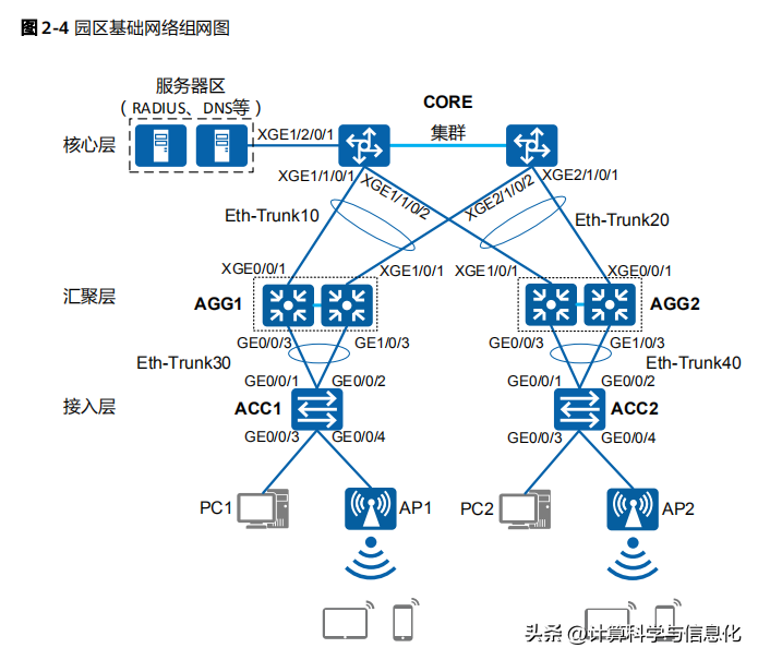
核心層使用兩臺框式交換機組建集群,匯聚層使用兩臺盒式交換機組建堆疊,核心層的集群與匯聚層的堆疊使用Eth-Trunk相連。
設備要求和版本
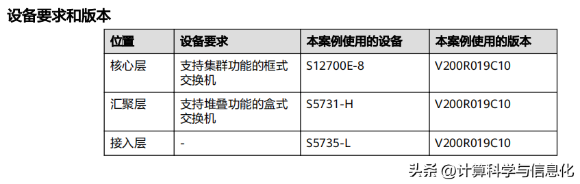
說明:不同款型的設備,堆疊、集群的連線方式和支持情況是有差異的,可以使用堆疊助手或查詢堆疊注意事項、框式集群注意事項獲取各款型的詳細信息。
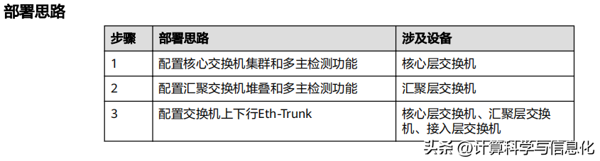
部署思路
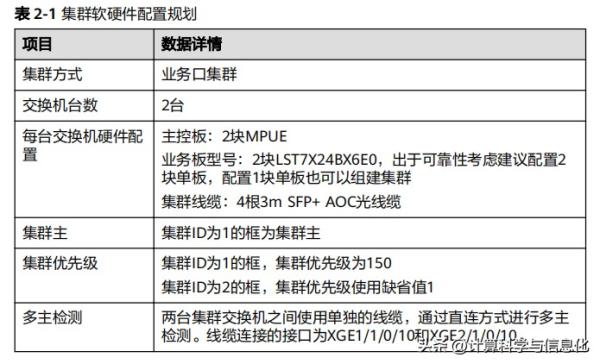
數據規劃


文章內容較長,建議收藏后觀看哦~
配置步驟
步驟1 搭建集群環境
1. 交換機下電,安裝用于集群業務板并根據下面連線圖連線集群線纜和多主檢測線纜。

說明:出于可靠性考慮,推薦按照下面方式進行連線:
- 一塊業務板上建議至少有兩個物理成員端口加入到一個邏輯集群端口。
- 上行端口和配置多主檢測的端口所在業務板建議屬于非組建集群的業務板。
2. 為兩臺交換機上電,按照數據規劃分別對兩臺框式交換機進行配置。
<HUAWEI> system-view
[HUAWEI] sysname Switch1
[Switch1] set css id 1
[Switch1] set css priority 150 //框1的集群優先級配置為150
[Switch1] interface css-port 1
[Switch1-css-port1] port interface xgigabitethernet 4/0/1 to xgigabitethernet 4/0/2 enable
[Switch1-css-port1] quit
[Switch1] interface css-port 2
[Switch1-css-port2] port interface xgigabitethernet 5/0/1 to xgigabitethernet 5/0/2 enable
[Switch1-css-port2] quit
[Switch1] display css status saved //查看集群配置是否正確
CSS port media-type: SFP+
Current Id Saved Id CSS Enable CSS Mode Priority Master force
------------------------------------------------------------------
1 1 Kff LPU 150 Kff
[Switch1] css enable //集群配置確認正確后,使能集群,重啟設備,為保證框ID成為主交換機,先重啟
Switch1
Warning: The CSS c?nfig?r?ì2?n will take ?ff?cì only after the system is rebooted. The next CSS mode
is CSS card. Reboot now? [Y/N]:y
<HUAWEI> system-view
[HUAWEI] sysname Switch2
[Switch2] set css id 2 //框2的集群優先級使用缺省值,不需要配置。
[Switch2] interface css-port 1
[Switch2-css-port1] port interface xgigabitethernet 4/0/1 to xgigabitethernet 4/0/2 enable
[Switch2-css-port1] quit
[Switch2] interface css-port 2
[Switch2-css-port2] port interface xgigabitethernet 5/0/1 to xgigabitethernet 5/0/2 enable
[Switch2-css-port2] quit
[Switch2] display css status saved //查看集群配置是否正確
CSS port media-type: SFP+
Current Id Saved Id CSS Enable CSS Mode Priority Master Force
1 2 Kff LPU 1 Kff
[Switch2] css enable //集群配置確認正確后,使能集群,重啟設備
Warning: The CSS c?nfig?r?ì2?n will take ?ff?cì only after the system is rebooted. The next CSS mode
is CSS card. Reboot now? [Y/N]:y
3. 交換機重啟后,查看集群是否組建成功。
#通過交換機框上主控板的集群指示燈查看集群狀態。
Switch1主控板上ACT燈綠色常亮,表示該主控板為集群系統主用主控板,Switch1為主交換機。
Switch2主控板上ACT燈綠色閃爍,表示該主控板為集群系統備用主控板,Switch2為備交換機。
#通過任意主控板上的Console口登錄集群系統,使用命令行查看集群組建是否成功。
根據集群優先級,優先級大的Switch1會成為集群系統的主框,執行命令displaydevice查看設備狀態時,集群系統名為Switch1。
<Switch1> display device
Chassis 1 (Master Switch)
S12700E-8's Device status:
Slot Sub Type Online Power Register Status Role
- - - - - - - - - - - - - - - - - - - - - - - - - - - - - - - - - - - - - -
1 - LST7X24BX6E0 Present PowerOn Registered Normal NA
2 - LST7X24BX6E0 Present PowerOn Registered Normal NA
3 - - Present PowerOn Unregistered - NA
9 - LST7MPUE0000 Present PowerOn Registered Normal Master
10 - LST7MPUE0000 Present PowerOn Registered Normal Slave
PWR1 - - Present PowerOn Registered Normal NA
CMU1 - EH1D200CMU00 Present PowerOn Registered Normal Master
FAN1 - - Present PowerOn Registered Normal NA
FAN2 - - Present PowerOn Registered Normal NA
Chassis 2 (Standby Switch)
S12700E-8's Device status:
Slot Sub Type Online Power Register Status Role
- - - - - - - - - - - - - - - - - - - - - - - - - - - - - - - - - - - - - - -
1 - LST7X24BX6E0 Present PowerOn Registered Normal NA
2 - LST7X24BX6E0 Present PowerOn Registered Normal NA
3 - - Present PowerOn Unregistered - NA
9 - LST7MPUE0000 Present PowerOn Registered Normal Master
10 - LST7MPUE0000 Present PowerOn Registered Normal Slave
PWR1 - - Present PowerOn Registered Normal NA
CMU2 - EH1D200CMU00 Present - Unregistered - NA
FAN1 - - Present PowerOn Registered Normal NA
FAN2 - - Present PowerOn Registered Normal NA
<Switch1> display css status
CSS Enable switch On
Chassis Id CSS Enable CSS Status CSS Mode Priority Master Force
-------------------------------------------------------------
1 On Master LPU 150 Kff
2 On Standby LPU 1 Kff
<Switch1> display css channel all //查看集群鏈路拓撲是否與硬件連接一致
CSS link-down-delay: 500ms
Chassis 1 || Chassis 2
=====================================
Num [CSS port] [LPU Port] || [LPU Port] [CSS port]
1 1/1 XGigabitEthernet1/4/0/1 XGigabitEthernet2/4/0/1 2/1
2 1/1 XGigabitEthernet1/4/0/2 XGigabitEthernet2/4/0/2 2/1
3 1/2 XGigabitEthernet1/5/0/1 XGigabitEthernet2/5/0/1 2/2
4 1/2 XGigabitEthernet1/5/0/2 XGigabitEthernet2/5/0/2 2/2
Chassis 2 || Chassis 1
=====================================
Num [CSS port] [LPU Port] || [LPU Port] [CSS port]
1 2/1 XGigabitEthernet2/4/0/1 XGigabitEthernet1/4/0/1 1/1
2 2/1 XGigabitEthernet2/4/0/2 XGigabitEthernet1/4/0/2 1/1
3 2/2 XGigabitEthernet2/5/0/1 XGigabitEthernet1/5/0/1 1/2
4 2/2 XGigabitEthernet2/5/0/2 XGigabitEthernet1/5/0/2 1/2
<Switch1> system-view
[Switch1] sysname CORE //為便于記憶,修改集群系統的設備名
4. 集群組建完成,配置多主檢測。
集群組建完成后,為防止集群故障分裂導致多主影響業務,在兩臺交換機直接連接一條線纜,用于多主檢測。線纜對應的接口分別為,如圖2-5所示。
[CORE] interface xgigabitethernet 1/1/0/10
[CORE-XGigabitEthernet1/1/0/10] mad detect mode direct
Warning: This command will block the port, and no other c?nfig?r?ì2?n running on this port is
recommended. Continue?[Y/N]:y [CORE-XGigabitEthernet1/1/0/10] quit
[CORE] interface xgigabitethernet 2/1/0/10
[CORE-XGigabitEthernet2/1/0/10] mad detect mode direct
Warning: This command will block the port, and no other c?nfig?r?ì2?n running on this port is
recommended. Continue?[Y/N]:y [CORE-XGigabitEthernet2/1/0/10] return
<CORE> display mad verbose //查看多主檢測配置
Current MAD domain: 0
Current MAD status: Detect
Mad direct detect interfaces c?nfig?r???
XGigabitEthernet1/1/0/10
XGigabitEthernet2/1/0/10
Mad relay detect interfaces c?nfig?r???
Excluded Y?rì?(c?nfig?r?b??)?
Excluded ports(can not be c?nfig?r??)
步驟2 搭建堆疊環境
這里以搭建堆疊AGG1為例,AGG2的搭建和配置過程與AGG1相同。
1. 按照數據規劃分別對兩臺盒式交換機進行配置。
說明:如果使用專用堆疊線纜堆疊,此步配置可以省略。
<HUAWEI> system-view
[HUAWEI] sysname Switch1
[Switch1] interface stack-port 0/1
[Switch1-stack-port0/1] port interface xgigabitethernet 0/0/3 xgigabitethernet 0/0/4 enable
Warning: Enabling stack function may cause c?nfig?r?ì2?n loss on the interface. Continue? [Y/N]:y
Info: This operation may take a few seconds. Please wait......
[Switch1-stack-port0/1] quit
[Switch1] stack slot 0 priority 150 //優先級設置為150,使其成為堆疊主
Warning: Please do not frequently modify Priority because it will make the stack split. Continue?
[Y/N]:y
[Switch1] quit
<Switch1> save //堆疊相關的配置不需要保存,會自動寫入fl??ˉ。為防止其他配置丟失,這里建議執行save命令進行保存
The current c?nfig?r?ì2?n will be written to fl??ˉ??
vrYcfg??2Y?
Are you sure to continue?[Y/N]y
Now saving the current c?nfig?r?ì2?n to the slot
0.......
Save the c?nfig?r?ì2?n successfully.
<HUAWEI> system-view
[HUAWEI] sysname Switch2
[Switch2] interface stack-port 0/2 //邏輯堆疊口1只能和邏輯堆疊口2相連,所以這里需要配置為邏輯堆疊口2
[Switch2-stack-port0/2] port interface xgigabitethernet 0/0/3 xgigabitethernet 0/0/4 enable
Warning: Enabling stack function may cause c?nfig?r?ì2?n loss on the interface. Continue? [Y/N]:y
Info: This operation may take a few seconds. Please wait......
[Switch2-stack-port0/2] quit
[Switch2] stack slot 0 renumber 1 //設置堆疊ID為1,使用缺省的堆疊優先級100
Warning: All the c?nfig?r?ì2?n? related to the slot ID will be lost after the slot ID is m??2fi???
Please do not frequently modify slot ID because it will make the stack split. Continue? [Y/N]:y
Info: Stack c?nfig?r?ì2?n has been changed, and the device needs to restart to make the
c?nfig?r?ì2?n ?ff?cì2v??
[Switch2] quit
<Switch2> save //堆疊相關的配置不需要保存,會自動寫入fl??ˉ。為防止其他配置丟失,這里建議執行save命令進行保存
The current c?nfig?r?ì2?n will be written to fl??ˉ??
vrYcfg??2Y?
Are you sure to continue?[Y/N]y
Now saving the current c?nfig?r?ì2?n to the slot
0.......
Save the c?nfig?r?ì2?n successfully
2. 交換機下電,根據下面連線圖連線堆疊線纜和多主檢測線纜。
圖2-6使用的是S5720-56C-HI-AC設備,堆疊接口和步驟1中配置的接口保持一致。

3. 交換機重啟后,查看堆疊是否組建成功。
<Switch1> display stack //堆疊組建成功,switch1是堆疊主
Stack mode: Service-port
Stack topology type : Ring
Stack system MAC: 0018-82d2-2e85
MAC switch delay time: 10 min
Stack reserved vlan : 4093
Slot of the active management port: --
Slot Role Mac address Priority Device type
---------------------------------------------------------
0 Master 0018-82d2-2e85 150 S5720-56C-HI-AC
1 Standby 0018-82c6-1f44 100 S5720-56C-HI-AC
<Switch1> system-view
[Switch1] sysname AGG1 //為便于記憶,修改堆疊系統的設備名
4. 堆疊組建完成,配置多主檢測。
堆疊組建完成后,為防止堆疊故障分裂導致多主影響業務,在兩臺交換機直接連接一條線纜,用于多主檢測。線纜對應的接口分別為GE0/0/10和GE1/0/10,如圖2-6所示。
[AGG1] interface gigabitethernet 0/0/10
[AGG1-GigabitEthernet0/0/10] mad detect mode direct
Warning: This command will block the port, and no other c?nfig?r?ì2?n running on this port is
recommended. Continue?[Y/N]:y
[AGG1-GigabitEthernet0/0/10] quit
[AGG1] interface gigabitethernet 1/0/10
[AGG1-GigabitEtherne/1/0/10] mad detect mode direct
Warning: This command will block the port, and no other c?nfig?r?ì2?n running on this port is
recommended. Continue?[Y/N]:y
[AGG1-GigabitEthernet1/0/10] return
<AGG1> display mad verbose //查看多主檢測配置
Current MAD domain: 0
Current MAD status: Detect
Mad direct detect interfaces c?nfig?r???
GigabitEthernet0/0/10
GigabitEthernet1/0/10
Mad relay detect interfaces c?nfig?r???
Excluded Y?rì?(c?nfig?r?b??)?
Excluded ports(can not be c?nfig?r??)?
步驟3
配置集群和堆疊之間的Eth-Trunk接口,以及堆疊和接入層交換機之間的Eth-Trunk接口。
1. 在集群上配置Eth-Trunk接口。
<CORE> system-view
[CORE] interface eth-trunk 10 //創建與AGG1相連的Eth-Trunk接口
[CORE-Eth-Trunk10] mode lacp
[CORE-Eth-Trunk10] quit
[CORE] interface xgigabitethernet 1/1/0/1
[CORE-XGigabitEthernet1/1/0/1] eth-trunk 10
[CORE-XGigabitEthernet1/1/0/1] quit
[CORE] interface xgigabitethernet 2/1/0/2
[CORE-XGigabitEthernet2/1/0/2] eth-trunk 10
[CORE-XGigabitEthernet2/1/0/2] quit
[CORE] interface eth-trunk 20 //創建與AGG2相連的Eth-Trunk接口
[CORE-Eth-Trunk20] mode lacp
[CORE-Eth-Trunk20] quit
[CORE] interface xgigabitethernet 1/1/0/2
[CORE-XGigabitEthernet1/1/0/2] eth-trunk 20
[CORE-XGigabitEthernet1/1/0/2] quit
[CORE] interface xgigabitethernet 2/1/0/1
[CORE-XGigabitEthernet2/1/0/1] eth-trunk 20
[CORE-XGigabitEthernet2/1/0/1] quit
2. 在堆疊AGG1上配置Eth-Trunk接口。
<AGG1> system-view
[AGG1] interface eth-trunk 10 //創建與集群相連的Eth-Trunk接口
[AGG1-Eth-Trunk10] mode lacp
[AGG1-Eth-Trunk10] quit
[AGG1] interface xgigabitethernet 0/0/1
[AGG1-XGigabitEthernet0/0/1] eth-trunk 10
[AGG1-XGigabitEthernet0/0/1] quit
[AGG1] interface xgigabitethernet 1/0/1
[AGG1-XGigabitEthernet1/0/1] eth-trunk 10
[AGG1-XGigabitEthernet1/0/1] quit
[AGG1] interface eth-trunk 30 //創建與接入層交換機ACC1相連的Eth-Trunk接口
[AGG1-Eth-Trunk30] mode lacp
[AGG1-Eth-Trunk30] quit
[AGG1] interface gigabitethernet 0/0/3
[AGG1-GigabitEthernet0/0/3] eth-trunk 30
[AGG1-GigabitEthernet0/0/3] quit
[AGG1] interface gigabitethernet 1/0/3
[AGG1-GigabitEthernet1/0/3] eth-trunk 30
[AGG1-GigabitEthernet1/0/3] quit
3. 在堆疊AGG2上配置Eth-Trunk接口。
<AGG2> system-view
[AGG2] interface eth-trunk 20 //創建與集群相連的Eth-Trunk接口
[AGG2-Eth-Trunk20] mode lacp
[AGG2-Eth-Trunk20] quit
[AGG2] interface xgigabitethernet 0/0/1
[AGG2-XGigabitEthernet0/0/1] eth-trunk 20
[AGG2-XGigabitEthernet0/0/1] quit
[AGG2] interface xgigabitethernet 1/0/1
[AGG2-XGigabitEthernet1/0/1] eth-trunk 20
[AGG2-XGigabitEthernet1/0/1] quit
[AGG2] interface eth-trunk 40 //創建與接入層交換機ACC2相連的Eth-Trunk接口
[AGG2-Eth-Trunk40] mode lacp
[AGG2-Eth-Trunk40] quit
[AGG2] interface gigabitethernet 0/0/3
[AGG2-GigabitEthernet0/0/3] eth-trunk 40
[AGG2-GigabitEthernet0/0/3] quit
[AGG2] interface gigabitethernet 1/0/3
[AGG2-GigabitEthernet1/0/3] eth-trunk 40
[AGG2-GigabitEthernet1/0/3] quit
4. 在接入層交換機ACC1上配置Eth-Trunk接口。
<ACC1> system-view
[ACC1] interface eth-trunk 30 //創建與堆疊AGG1相連的Eth-Trunk接口
[ACC1-Eth-Trunk30] mode lacp
[ACC1-Eth-Trunk30] quit
[ACC1] interface gigabitethernet 0/0/1
[ACC1-GigabitEthernet0/0/1] eth-trunk 30
[ACC1-GigabitEthernet0/0/1] quit
[ACC1] interface gigabitethernet 0/0/2
[ACC1-GigabitEthernet0/0/2] eth-trunk 30
[ACC1-GigabitEthernet0/0/2] quit
5. 在接入層交換機ACC2上配置Eth-Trunk接口。
<ACC2> system-view
[ACC2] interface eth-trunk 40 //創建與堆疊AGG2相連的Eth-Trunk接口
[ACC2-Eth-Trunk40] mode lacp
[ACC2-Eth-Trunk40] quit
[ACC2] interface gigabitethernet 0/0/1
[ACC2-GigabitEthernet0/0/1] eth-trunk 40
[ACC2-GigabitEthernet0/0/1] quit
[ACC2] interface gigabitethernet 0/0/2
[ACC2-GigabitEthernet0/0/2] eth-trunk 40
[ACC2-GigabitEthernet0/0/2] quit
----結束
配置腳本
說明:集群和堆疊的配置不記入配置文件,直接寫入Flash,所以配置文件中沒有堆疊和集群相關的配置,只有多主檢測和Eth-Trunk接口的配置。
● 集群配置文件

● AGG1堆疊配置文件

● AGG2堆疊配置文件

● ACC1配置文件

● ACC2配置文件

*內容整理自華為官方,僅為分享使用
---END---
轉載自頭條號:計算科學與信息化。(侵刪)